Magnetic Particle Inspection (MPI) — A Complete Guide
Magnetic Particle Inspection (MPI) — also designated MT (Magnetic Testing) under ASNT and ISO terminology — is one of the most widely used non-destructive testing methods for detecting surface and near-surface discontinuities in ferromagnetic materials. It is fast, cost-effective, portable, and capable of revealing tight surface cracks that would be invisible to the naked eye. From pipeline girth welds and pressure vessel shell seams to turbine shafts, crane hooks, and offshore structural connections, MPI is applied wherever the integrity of ferromagnetic components is safety-critical.
The principle is elegant: establish a magnetic flux in the material, and any surface or shallow subsurface discontinuity that interrupts that flux will cause the field to leak at the surface. Fine ferromagnetic particles applied at that moment are attracted to and bridge the leakage field, forming a visible indication. The shape, length, and orientation of that indication give the inspector direct information about the nature and extent of the flaw.
This guide covers every element of the MPI process in depth — from magnetisation physics and current selection through particle media, technique geometry, acceptance criteria, demagnetisation, and all relevant ASTM, ISO, and EN standards. Whether you are preparing for a welding inspection certification or conducting MPI on a pressure vessel HAZ, you will find the practical detail you need here.
Physics of Magnetisation in MPI
When an external magnetic field is applied to a ferromagnetic material, the magnetic domains — microscopic regions of aligned atomic magnetic moments — rotate to align with the applied field. The material becomes magnetised and supports a high flux density. Where the material is continuous, the flux travels within it with low reluctance (magnetic resistance). A discontinuity — a crack, lack of fusion, or inclusion — has much higher reluctance than the surrounding steel, so the flux is forced to detour. If the discontinuity intersects or lies close to the surface, the flux detour causes a leakage field above the surface that can attract and hold ferromagnetic particles.
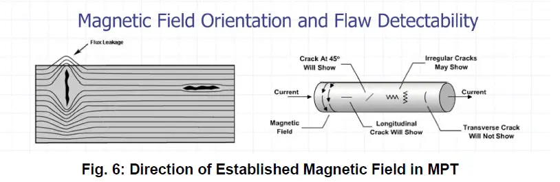
Flux Direction and Defect Orientation
Detection sensitivity is strongly dependent on the angle between the magnetic flux and the defect plane. Maximum sensitivity occurs when flux crosses the defect at 90°; sensitivity falls to zero when flux runs parallel to the defect (0°). Industry standards require that all areas be inspected at two directions at least 45°–90° apart to ensure no orientation of defect escapes detection. This is why every MPI procedure specifies both a longitudinal magnetisation step (to detect transverse cracks) and a circular/transverse step (to detect longitudinal cracks).
Magnetisation Techniques
Yoke Technique
The electromagnetic yoke is the most common field inspection tool. A U-shaped core wound with an electromagnet is placed on the part surface; the two poles of the yoke complete the magnetic circuit through the workpiece, inducing a longitudinal field between the poles. AC yokes must demonstrate a minimum lifting force of 4.5 kg (10 lb), while DC and permanent magnet yokes must demonstrate at least 18 kg (40 lb) to confirm adequate field strength — per ASTM E1444 and ASTM E709.
The effective inspection zone (EIZ) between the poles is approximately one-third of the pole spacing from each pole, leaving a dead zone directly under each pole. Poles are typically spaced 75–200 mm apart, and the part must be inspected with the yoke in at least two orientations perpendicular to each other.
Central Conductor (Threading Bar) Technique
A copper rod or cable is threaded through a hollow part (pipe, ring, cylinder) and current is passed through it. The current generates a circular magnetic field around the conductor and through the surrounding part walls, enabling detection of longitudinal and radial discontinuities on both inner and outer surfaces. This is widely used for tubular components and pipe fittings.
Prod Technique
Two hand-held prods are pressed onto the part surface and current is passed directly through the material between them. This creates a circular field around the current path and is effective for detecting longitudinal and diagonal cracks. Prod spacing is typically 75–200 mm. The technique requires careful control of current to prevent arc burns at the prod contact points, which are potential stress risers and create metallurgical damage in the HAZ — arc burns must be recorded and may require repair per many codes.
Head Shot / Direct Contact
The part is clamped directly between current-carrying contacts in a fixed bench unit. Current flows through the entire length of the part, creating a strong circular field. This is the most productive technique for batch inspection of machined parts in a workshop setting.
Coil Technique
The part is placed inside a current-carrying coil or solenoid, which induces a longitudinal (axial) field along the part length. This is complementary to the circular field from head shots and together they provide complete circumferential and longitudinal coverage.
Electrical Current Types in MPI
The choice of magnetising current fundamentally affects penetration depth, particle mobility, and the type of discontinuities detectable. Each has specific use cases and limitations.
| Current Type | Penetration Depth | Particle Mobility | Primary Use | Limitations |
|---|---|---|---|---|
| AC (Alternating Current) | Surface only | High — AC agitates particles | Surface-breaking fatigue cracks, grinding cracks | Skin effect limits depth to ~1 mm; cannot detect subsurface indications |
| Full-Wave DC (FWDC) | Moderate — ~3 mm | Lower than AC | Subsurface inclusions, porosity near surface | Requires rectifier; less particle mobility than AC |
| Half-Wave DC (HWDC) | Moderate — ~3–6 mm | Good — pulsating field aids migration | Subsurface cracks and inclusions; preferred for weld inspection | Requires rectifier; higher residual magnetism than AC |
| Permanent Magnet Yoke | Surface only | Moderate | Intrinsically safe environments (no mains supply) | Fixed field strength; no particle agitation; heavy |
Magnetic Particle Media — Dry vs Wet Methods
Dry Particle Method
Dry particles are finely divided iron powder coated with a coloured pigment (red oxide, black, grey, yellow) for contrast against the part surface. They are applied by puffing, spraying, or shaking onto the magnetised surface. Advantages include suitability for rough surfaces, elevated temperatures up to ~315°C, and remote field applications. The primary limitation is lower sensitivity to fine, tight cracks compared to wet methods, because dry particles are heavier and migrate less effectively to shallow leakage fields.
Wet Particle Method
Wet particles are suspended in a carrier vehicle — either a light petroleum oil or a water-based conditioned bath — at a typical concentration of 1.2–2.4 mL (solids) per 100 mL of bath. The liquid carrier allows particles to flow freely across the surface and migrate readily to weak leakage fields, providing higher sensitivity for fine cracks. Concentration is verified daily using a centrifuge tube (ASTM E1444 Appendix A2).
Fluorescent Wet Particles
Fluorescent particles are coated with a fluorescent dye that glows bright yellow-green under UV-A (ultraviolet) light at 365 nm wavelength. This technique offers the highest sensitivity of all MPI methods because the contrast between the glowing indication and the dark background is far greater than any visible-light method. It is required by many aerospace and nuclear standards and is the technique of choice for critical pressure equipment welds. The UV-A lamp must provide a minimum irradiance of 1,000 µW/cm² at the inspection surface, and ambient light must not exceed 2 foot-candles (20 lux) per ASTM E1444.
Visible (Non-Fluorescent) Particles
- Inspected under white light (≥500 lux at surface)
- Contrast paint may be applied first (dark surfaces)
- Lower sensitivity than fluorescent
- Suitable for field, general fabrication, and structural inspection
- Colours: red, black, grey, yellow
Fluorescent Particles
- Inspected under UV-A light in darkened conditions
- Minimum UV-A irradiance: 1,000 µW/cm² (ASTM E1444)
- Highest sensitivity — detects very fine tight cracks
- Required for aerospace, nuclear, and critical pressure vessels
- Bath concentration checked daily by centrifuge tube
Step-by-Step MPI Procedure
- Surface Preparation Remove scale, weld spatter, heavy rust, grease, oil, and any paint thicker than 0.13 mm (0.005 inch). A thin, even white contrast coat may be applied on dark surfaces for visible particle work. Verify surface is dry (or suitably wet for wet method).
- Equipment and Material Verification Verify UV lamp irradiance (≥1,000 µW/cm²) if fluorescent, or white light level (≥500 lux). Check yoke lifting force (AC yoke: ≥4.5 kg; DC yoke: ≥18 kg). Verify bath concentration by centrifuge tube if wet method. Record calibration status of all equipment.
- Magnetisation — Direction 1 Apply magnetisation in the first direction using the selected technique (yoke, prod, coil, or direct contact). Apply particles during or immediately after energisation. For the yoke technique, index (overlap) each position by at least one pole width.
- Particle Application and Inspection Apply particles uniformly while the field is active. For dry particles, use a light, even application — excess particles mask indications. For wet method, apply by bath flow or spray. Inspect under appropriate lighting; allow adequate viewing time (minimum 1 second per zone).
- Magnetisation — Direction 2 (Perpendicular) Repeat steps 3 and 4 with the magnetising field rotated approximately 90° from the first direction. This second pass ensures that defects parallel to the first field direction are now crossing the field and will form indications.
- Indication Identification and Evaluation Examine all indications. Classify as relevant (caused by a discontinuity), non-relevant (caused by geometry — edges, threads, press fits), or false (caused by contamination or improper technique). Relevant indications must be sized and compared against acceptance criteria.
- Demagnetisation Demagnetise the part to reduce residual flux to below the specified maximum (typically <3 Gauss / 0.3 mT). Use AC demagnetising coil or progressive DC decay method. Verify with a Hall-effect meter or compass after demagnetisation.
- Post-Cleaning and Reporting Remove all particle residue, contrast paint, and carrier fluid. Apply corrosion inhibitor if required. Prepare the MPI report documenting: procedure reference, equipment used, particle type and concentration, magnetisation method and current, all indications found (with location sketch or photograph), acceptance/rejection disposition, and inspector certification level.
Indication Classification and Acceptance Criteria
Not all particle accumulations represent rejectable defects. The inspector must distinguish between three categories:
| Indication Type | Definition | Action Required |
|---|---|---|
| Relevant | Caused by a genuine flux leakage at a material discontinuity. Length > 1.5 mm is typically considered relevant. | Size and compare against applicable acceptance standard. Accept, reject, or repair as required. |
| Non-Relevant | Caused by geometric transitions — edges, keyways, thread roots, press-fit interfaces — not by defects. | Document and confirm geometry is the cause. No rejection action, but record in report. |
| False | Caused by contamination, excessive particles, or improper technique. Not from a discontinuity. | Clean area and re-inspect. Do not dismiss without re-inspection confirmation. |
Typical Acceptance Criteria (ASME and ISO)
Acceptance criteria vary by construction code and application. The following are typical for pressure vessel and piping weld inspection:
| Code / Standard | Application | Rejectable Indication Criteria |
|---|---|---|
| ASME Sec. VIII Div. 1 (App. 6) | Pressure vessels — MT of welds | Any linear indication > 6 mm; rounded indication > 5 mm; four or more rounded indications in a line spaced ≤ 1.5 mm edge-to-edge |
| ASME B31.3 (Appendix 8 / ASME B31.3) | Process piping welds | Linear indication > 6 mm; rounded > 5 mm; group of four or more aligned ≤ 1.5 mm apart |
| ISO 23279 | Welds — acceptance levels 1–3 | Level 1 (most stringent): linear indications not permitted; rounded ≤ 2 mm. Level 3 (less stringent): linear ≤ 8 mm; rounded ≤ 5 mm |
| AWS D1.1 (Clause 6.11) | Structural steel welds | Cracks not permitted; linear indication > 6 mm is rejectable; rounded > 10 mm is rejectable |
Advantages and Limitations of MPI
| Criterion | Advantages | Limitations |
|---|---|---|
| Material Applicability | Applicable to all ferromagnetic materials including carbon steel, alloy steel, and cast iron | Only ferromagnetic materials. Cannot test austenitic stainless, aluminium, titanium, or copper alloys |
| Defect Detection Sensitivity | Detects both surface-breaking and near-subsurface defects; can detect smeared-over defects that LPT would miss | Maximum reliable subsurface detection depth ~3 mm (up to 6 mm under ideal HWDC conditions) |
| Portability and Cost | Yoke equipment is highly portable and low cost; suitable for in-situ inspection of large fabrications and structures | Paint > 0.13 mm (0.005 inch) must be removed; requires surface preparation time |
| Speed | Rapid inspection with immediate visible results; suitable for production line inspection | Post-inspection cleaning, demagnetisation, and reporting add time |
| Part Geometry | Can inspect irregular shapes: external splines, crankshafts, connecting rods, weld toes, complex castings | Large flat areas require multiple overlapping yoke positions; throughput lower than automated UT on production lines |
| Defect Orientation Dependency | With two-direction magnetisation, all orientations of defect are covered | A single-direction technique will miss defects parallel to the flux; operator must apply two perpendicular fields |
| Direct Indication | Indications form directly on the part surface — no imaging, film, or data processing required for initial evaluation | Fluorescent method requires darkened inspection booth and UV-A equipment; white-light method has lower sensitivity |
MPI in Relation to Other NDT Methods
MPI occupies a specific niche in the NDT toolkit. Compared to other NDT methods:
Liquid Penetrant Testing (LPT) is the alternative surface-crack method for non-ferromagnetic materials. LPT is slightly slower and requires more surface cleanliness, but it works on any solid material — making it the method of choice for austenitic stainless steel, aluminium, and titanium welds. Where both MPI and LPT are applicable (e.g., ferritic steel), MPI is generally preferred because it also detects near-subsurface indications and can detect cracks that have been mechanically smeared over.
Ultrasonic testing (UT) provides volumetric coverage and can detect internal defects at any depth, but it requires skilled operators, trained scanning patterns, and is less sensitive to tight surface-breaking cracks than MPI. Many codes require MPI or LPT for surface examination and UT for volumetric examination — they are complementary rather than competing. See the ASME Section IX mechanical and NDE testing guide for how the two methods interact in weld procedure qualification.
Radiography (RT) provides a permanent record of the weld cross-section but cannot detect tight planar cracks reliably and requires radiation safety controls. MPI is far more sensitive to surface cracks and is significantly faster and lower-cost for surface examination.
MPI of Welded Joints — Special Considerations
In welding fabrication, MPI is most commonly applied to detect post-weld cracks (hydrogen-induced cold cracking, reheat cracking), toe cracks in fillet and partial-penetration welds, root cracks in pipe butt welds, and grinding cracks introduced during weld dressing. Several considerations apply specifically to welds:
Post-Weld Inspection Timing
For steels susceptible to hydrogen-induced cold cracking — particularly high-carbon equivalent steels, hardenable low-alloy steels such as P91 / Grade 91, and certain high-strength structural grades — hydrogen diffusion and delayed cracking may not be complete until 24–48 hours after welding. ASME B31.3 and many pressure vessel codes require that MT of susceptible welds be deferred until at least 48 hours after completion of welding to avoid false acceptance of joints that will later crack. The carbon equivalent calculator can help identify whether a steel is in a susceptibility range requiring delayed inspection.
Post-PWHT Inspection
Where post-weld heat treatment (PWHT) is specified, MPI should normally be performed after PWHT, because the thermal cycle of PWHT can itself generate or open reheat cracks — particularly in alloy steels such as Cr-Mo grades. Performing MPI before PWHT would miss such defects. However, some codes require inspection both before and after PWHT.
Weld Surface Condition
Weld cap ripples, undercut, and spatter all create magnetic irregularities that generate non-relevant indications (geometric pseudo-indications). Wherever possible, the weld surface should be ground or dressed to a smooth contour before MPI to reduce spurious indications and improve signal-to-noise ratio. When inspecting as-welded surfaces, the inspector must have experience distinguishing geometric non-relevant indications from genuine defect indications.
Demagnetisation — Principles and Practice
Residual magnetism left in a part after MPI can cause problems in subsequent operations: it attracts ferrous swarf during machining, interferes with arc stability during welding (magnetic arc blow), and can affect electromagnetic measuring instruments. Most codes require demagnetisation to below 3 Gauss (0.3 mT).
AC Coil Demagnetisation
The part is passed through an AC coil at a rate that allows the alternating field to progressively reduce as the part moves away from the coil centre. The diminishing alternating field cycles the magnetic domains through progressively smaller hysteresis loops until residual magnetism is negligible. This is the most common workshop method for small to medium parts.
DC Reversal Demagnetisation
For large parts that cannot be moved through a coil, a DC field is applied and then reversed at decreasing amplitudes in a step-down sequence. Modern electronic demagnetisers automate this cycle. Verification must always follow demagnetisation — a Hall-effect meter or compass deviation test confirms the residual field is below specification.
Applicable Standards — Complete Reference
ISO Standards
- ISO 3059 — Non-destructive testing: Penetrant testing and magnetic particle testing — Viewing conditions
- ISO 9934-1 — Magnetic particle testing — Part 1: General principles
- ISO 9934-2 — Magnetic particle testing — Part 2: Detection media
- ISO 9934-3 — Magnetic particle testing — Part 3: Equipment
- ISO 17638 — Non-destructive testing of welds: Magnetic particle testing
- ISO 23279 — Non-destructive testing of welds: Magnetic particle testing — Acceptance levels
ASTM Standards
- ASTM E1444 — Standard Practice for Magnetic Particle Testing (primary general practice standard)
- ASTM E709 — Guide for Magnetic Particle Testing (comprehensive guidance document)
- ASTM A275 / A275M — Test Method for Magnetic Particle Examination of Steel Forgings
- ASTM A456 — Specification for Magnetic Particle Inspection of Large Crankshaft Forgings
- ASTM E543 — Practice for Evaluating Agencies that Perform NDT
- ASTM E1316 — Terminology for Nondestructive Examinations
- ASTM E2297 — Guide for Use of UV-A and Visible Light Sources used in Liquid Penetrant and Magnetic Particle Methods
EN / CEN Standards
- EN 1330-7 — Non-destructive testing — Terminology — Part 7: Terms used in magnetic particle testing
- EN 1369 — Founding: Magnetic particle inspection
- EN 10228-1 — Non-destructive testing of steel forgings — Part 1: Magnetic particle inspection
- EN 10246-12 — Non-destructive testing of steel tubes — Part 12: Magnetic particle inspection of seamless and welded ferromagnetic steel tubes
- EN 10246-18 — Non-destructive testing of steel tubes — Part 18: Magnetic particle inspection of tube ends for laminar imperfections